To use all functions of this page, please activate cookies in your browser.
My watch list
my.bionity.com
my.bionity.com
With an accout for my.bionity.com you can always see everything at a glance – and you can configure your own website and individual newsletter.
- My watch list
- My saved searches
- My saved topics
- My newsletter
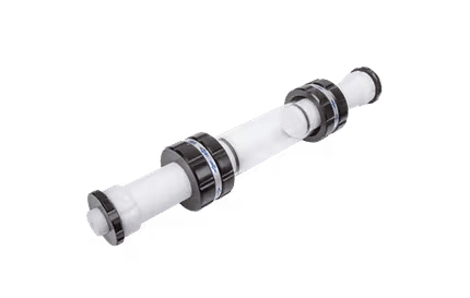
Resistance thermometerResistance thermometers, also called resistance temperature detectors (RTDs), are temperature sensors that exploit the predictable change in electrical resistance of some materials with changing temperature. As they are almost invariably made of platinum, they are often called platinum resistance thermometers (PRTs). They are slowly replacing the use of thermocouples in many industrial applications below 600 °C. Product highlightGeneral descriptionThere are two broad categories, "film" and "wire-wound" types.
The current international standard which specifies tolerance and the temperature to electrical resistance relationship for platinum resistance thermometers is IEC 751:1983. By far the most common devices used in industry have a nominal resistance of 100 ohms at 0 °C, and are called Pt-100 sensors ('Pt' is the symbol for platinum). The sensitivity of a standard 100 ohm sensor is a nominal 0.385 ohm/°C. RTDs with a sensitivity of 0.375 and 0.392 ohm/°C are also available. How do resistance thermometers work?Resistance thermometers are constructed in a number of forms and offer greater stability, accuracy and repeatability in some cases than thermocouples. While thermocouples use the Seebeck effect to generate a voltage, resistance thermometers use electrical resistance and require a small power source to operate. The resistance ideally varies linearly with temperature. Resistance thermometers are usually made using platinum, because of its linear resistance-temperature relationship and its chemical inertness. The platinum detecting wire needs to be kept free of contamination to remain stable. A platinum wire or film is supported on a former in such a way that it gets minimal differential expansion or other strains from its former, yet is reasonably resistant to vibration. RTD assemblies made from iron or copper are also used in some applications. Commercial platinum grades are produced which exhibit a change of resistance of 0.385 ohms/°C (European Fundamental Interval) The sensor is usually made to have a resistance of 100Ω at 0 °C. This is defined in BS EN 60751:1996 (taken from IEC 60751:1995) . The American Fundamental Interval is 0.392 Ω/°C, based on using a purer grade of platinum than the European standard. The American standard is from the Scientific Apparatus Manufacturers Association (SAMA), who are no longer in this standards field. Resistance thermometers require a small current to be passed through in order to determine the resistance. This can cause resistive heating, and manufacturers' limits should always be followed along with heat path considerations in design. Care should also be taken to avoid any strains on the resistance thermometer in its application. Lead wire resistance should be considered, and adopting three and four wire connections can eliminate connection lead resistance effects from measurements - industrial practice is almost universally to use 3-wire connection. Advantages and limitationsAdvantages of platinum resistance thermometers:
Limitations:
Resistance thermometer elementsResistance thermometer elements are available in a number of forms. The most common are:
Resistance thermometer construction
Resistance thermometer wiring configurationsTwo-wire configuration
Three-wire configuration
Four-wire configuration
HistoryThe application of the tendency of electrical conductors to increase their electrical resistance with rising temperature was first described by Sir William Siemens at the Bakerian Lecture of 1871 before the Royal Society of Great Britain. The necessary methods of construction were established by Callendar, Griffiths, Holborn and Wein between 1885 and 1900. Standard resistance thermometer dataTemperature sensors are usually supplied with thin-film elements. These are rated in accordance with BS EN 60751:1996 as:
Resistance thermometer elements can be supplied which function up to 850 °C. Sensor tolerances are calculated as:
where |t| = absolute value of temperature in °C. Where elements have a resistance of n x 100 Ω then the basic values and tolerances also have to be multiplied by n. Temperature to resistance equationThe relation between temperature and resistance is given by the Callendar-Van Dusen equation, Here, RT is the resistance at temperature T, R0 is the resistance at 0 °C, and the constants (for an alpha=0.00385 platinum RTD) are Since the B and C coefficients are relatively small, the resistance changes almost linearly with the temperature. ReferencesText and images used by permission of Peak Sensors Ltd: Resistance Thermometer Information See also
|
||||||||||||||||||||
| This article is licensed under the GNU Free Documentation License. It uses material from the Wikipedia article "Resistance_thermometer". A list of authors is available in Wikipedia. |

![R_T = R_0 \left[ 1 + AT + BT^2 + cT^3 (T-100) \right] \; (-200\;{}^{\circ}\mathrm{C} < T < 0\;{}^{\circ}\mathrm{C}),](images/math/1/b/2/1b2b866a4b043bc4ced08de262cdbb8f.png)
![R_T = R_0 \left[ 1 + AT + BT^2 \right] \; (0\;{}^{\circ}\mathrm{C} \leq T < 850\;{}^{\circ}\mathrm{C}).](images/math/9/a/8/9a8ee16cacd873b4592af95df3dddfc1.png)


Last viewed


